MSI product lines can be broadly distributed into 5 broad categories, excluding the PRO and CREATOR offerings, they have three lineups targeted towards gamers, Kicking off the categories is the top-end series – MEG (MSI Enthusiast Gaming), the very absolute best, – MPG (MSI Performance Gaming), which is a great middle-ground of value and quality – MAG (MSI Arsenal Gaming ), which is the more value-oriented line up from MSI. Tomahawk models have been the flagship of their MAG offerings for several years and have managed to prove themselves worthy of appreciation, Making it one of the hottest entry-level boards in the market right now.
MSI was kind enough to send over the MAG B550 TOMAHAWK and we made it run through our paces. Read on to find out what we have to say about it.
Right off the bat, we could see that the reinforced VRM section is equipped with massive heat sinks, and the rear I/O cover is now integrated with this heatsink. We also saw an ample implementation of PWM headers for pumps and fans, all of which can be controlled from the BIOS or the MSI center utility. The network infrastructure includes a couple of controllers, both from Realtek. However, we saw an absence of any pre-installed wireless networking modules. The main features of the board is shown in the table below:
| Feature | Description |
|---|---|
| Socket | AMD AM4 |
| Processors | AMD Series: Ryzen 3, Ryzen 5, Ryzen 7, Ryzen 9 |
| Memory | 4 DIMM DDR4 SDRAM, 128 GB maximum: 1866-3200 – JEDEC, 2667-5100 + – A-XMP (OC) |
| PCI-E slots | 1 x PCI Express 4.0 x16 (x16) – CPU, 1 x PCI Express 3.0 x16 (x8) – APU, 1 x PCI Express 3.0 x16 (x4) – B550, 2 x PCI Express 3.0 x1 – B550 |
| M.2 slots | 1 x PCI Express 4.0 x4, SATA (Key M, 2242/2260/2280/22110) – Ryzen 3rd Gen CPU, 1 x PCI Express 3.0 x4 (Key M, 2242/2260/2280) – B550 |
| Display Outputs | DisplayPort, HDMI |
| PWM Headers | 8x 4 pin PWM |
| PS/2 Ports | 1 |
| USB Ports | 2 x 3.2 Gen2 (2 connectors on the rear panel (1x C), CPU), 2 x 3.2 Gen1 (2 connectors on the rear panel, CPU), 3 x 3.2 Gen1 (no connectors on the rear panel, B550), 6 x 2.0 (2 connectors on rear panel, B550) |
| SATA | 6 x SATA 6Gb / s (B550) |
| RAID | 0, 1, 10 (SATA), 0, 1 (M.2 NVMe) |
| Built-in Sound | Codec – Realtek ALC1200 (7.1, HDA) |
| S / PDIF | Optical (output) |
| Networking Capabilities | Realtek RTL8111H (Gigabit Ethernet), Realtek RTL8125B (2.5 Gigabit Ethernet) |
| ARGB Header | 2 |
| RGB Header | 2 |
| BIOS Chip | UEFI AMI BIOS, 256 Mb Flash ROM (MX25U25673G) |
| TPM | 1x SPI (12 pin) |
| Additional features | EZ Debug LED (CPU, DRAM, VGA, BOOT LED), EZ LED Control switch, Flash BIOS Button, M.2 with Shield Frozr; AMD 2-Way CrossFireX support |
UNBOXING
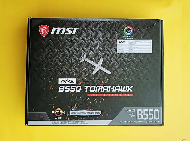
The board comes securely packed in an extra thick cardboard box. The inscriptions on the front of the box divulge some details like, 5000 series ready, PCI-e 4.0 ready, model of the board. It also flaunts the support for MSI Mystic light.
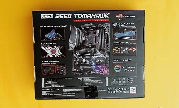
The rear of the box again lists some of the USPs, like, provision of extended heatsinks for the VRM section, support for the famous MSI CoreBoost Technology, 2.5G lan, PCI-e 4.0 Storage support, and rear IO layout.

On opening the box we find the board securely packed in an anti static bag.

Keeping the board aside for now, we see a bunch of documentation and some essential equipment like 2X SATA cables, some M.2 standoffs and mounting screws.
What’s in the Box?

The Tomahawk comes with only the bare essentials and some literature out of the box.
Closer Look
Here are a few shots highlighting some of the features, provided by the board, which are worth mentioning.
APPEARANCE

This time around we see the board is surprisingly heavy. However, this isn’t weird and was expected with the provision of those enlarged heatsinks and that thick PCB.
However, I was somewhat surprised when I found the underside of the board has now lost its RGB implementation, voiding the board of that awesome underglow.

The chipset heatsink is a huge monolithic block with the word “TOMAHAWK” inscribed across it. The overall design language of the board is carried over here too. It is to be noted here, that the only lighting implementation on the board is under this shroud, in the form of 6 LEDs scattered around the chipset in equal intervals. However, all these efforts shall be canceled out, the moment you install a beefy GPU. I should mention at this point that the pre-applied thermal paste on the chipset is good for a single inspection. We didn’t know this, so we had to clean out the residue and re-apply classic thermal paste, in our case the Noctua NT-H1.
While we are on the point of the chipset, here is a glimpse of the B550 Chip on the Tomahawk.


The top M.2 slot supports devices up to a maximum length of 110mm, ie, 22110 devices. However, the bottom Slot supports a maximum of 80mm, ie, the 2280 devices.

We also see the board supports a total of 6 SATA devices, which seems to be the norm and standard at the moment.

There is no shielding around the sound subsystem, but all of it is shifted to the bottom corner – away from the CPU and VC.


Despite using the lower-end Realtek ALC1200 audio codec, compared to the common ALC1220, MSI’s B550 MAG Tomahawk delivers ‘Very Good’ overall audio performance.

LED_SW1 (EZ LED Control switch) allows you to instantly turn off the backlight. This comes in very handy when you don’t like RGB and prefer to keep it switched off without downloading any utilities.

There is no indicator for POST codes, which is to be expected from a board of this caliber. However, a set of four red EZ Debug LEDs is provided which can help you dramatically while you face issues with your hardware.


Msi is actually deploying a 10+2+1 stage power delivery solution. So you got 10 stages dedicated to the CPU 2 for the SOC and 1 for the APU. All these stages are managed by the RAA229004 PWM controller from Renesas Electronics. MSI didn’t use any phase doublers so this config is running in a 5+2 orientation and therefore is using a teamed design in parallel operation for the DRMos. The ten teamed power stages that are controlled by the five PWM controller phases are the Intersil ISL99360. A feature of these chips is an integrated temperature sensor. The power stages are rated for up to 60 amps of output. They can often be found in more higher end boards, and are a very smart option. I was a bit surprised with the decision of going with a single 8 pin EPS power. I guess the target audience for the tomahawk won’t be needing more but it would have been awesome to see another 4 pin.

The provided heatsinks for the VRM makes great contact with the components and features very high quality thermal pads.


From left to right we have the BIOS Flashback button. Next we have 2×2.0 USB ports, followed by 1x HDMI and 1x DisplayPort. Next, we see one 2.5G lan and 2x USB 3.2 Gen1 (5GBPS) Type-A ports, then another 1 Gig lan followed by 1x Type A and 1x type C USB 3.2 Gen 2 10 Gbps, and then we have the audio section.
BOARD INSCRIPTIONS
The Tomahawk comes with a lot of information inscribed right on the board. These inscriptions come in very handy for first time or novice builders.

Clear Inscriptions showing the front panel connectors location.

The board advertises support for MSI CORE BOOST and DDR4 BOOST technology.

We can see clear inscriptions stating the locations of the VCC and GND pins for both the USB 2.0 Headers.

The inscription near the top M.2 Slot shows all the necessary information about that slot. Including the lane source and also the supported devices.

This is also the case for the lower M.2 Slot.

The DIMM slots also come labeled as to which slots should be populated first to take advantage of the dual channel memory. This one is a life saver. We have seen hundreds of builds with misconfigured RAMs, over the years.
PCB QUALITY

Striped down and bare look at the PCB.

We were very satisfied with the PCB quality. The PCB had almost zero flex, and was very thick. The finish on the PCB is very soothing too, which is mostly for aesthetic brownie points.
INTERNAL CONNECTORS AND HEADERS

At the bottom end of the board we have the following connectors, Listed left to right.
- Front Panel Audio
- 1 x 4 PIN 12V Universal RGB Header
- 1 PWM Header
- LED Switch
- 1 PWM header
- 2 X USB 2.0 Header
- 1 X USB 3.0 Header
- 1 x 4 PIN 12V Universal RGB Header
- Front Panel Connector Headers
- Universal 5V 3 PIN ARGB Header
- Another PWM Header

At the top of the board we see a couple more headers.
1 X 3 PIN 5V Universal ARGB Header
1 X PWM Header designated for PUMP
1 X PWM Header designated for CPU Fan.
HARDWARE COMPATIBILITY ISSUES
While working with the MSI B550 TOMAHAWK we found a couple of weird design choices which can become a potential hardware compatibility issues :-

The USB 3 Header is placed at a very uncommon location, we understand that this location was chosen to make cable management easier near the 24PIN cable. This choice makes it very difficult to install this board in a case with bottom fans. This creates a risk factor for the header being ripped out or getting bent over time.

The battery is located at such a point where it will be next to impossible to remove the battery, to clear CMOS or maybe some other use scenario, without removing the GPU which can be a bit of a problem over time if you are trying out some OC settings, which might be stopping your PC from successfully POSTing. What makes it even more frustrating is the fact that the clear CMOS jumper pins are situated right next to it.
UEFI AND UTILITY


MSI BIOS is one of the cleanest and easiest to navigate in my opinion.
Testing and Benchmarks.
There are a lot of sensors on board, so here are all the sensors that AIDA could pickup.


This board uses the Realtek RTL8125 2.5GBe Ethernet controller and the RTL8168/8111 controller for the gigabit ethernet.
Here is the breakdown of the components used in our test bench.
| Component | Description |
|---|---|
| Processor | AMD Ryzen 5 4650G |
| Cooler | Cooler Master ML360R |
| Motherboard | MSI B550 Tomahawk |
| RAM | ANTEC KATANA |
| GPU | ASUS ROG STRIX 1070 |
| Case | LIAN LI O11 DYNAMIC |
| PSU | ANTEC HCG 750W GOLD |
| OS | WINDOWS 11 PRO |
Benchmarks
Geekbench 5 Single core:-
The benchmark was carried out in 3 different configurations,
- Stock PBO Boost
- 4000 MHz
- 4200 MHz
- 4300 MHz
- 4400 MHz
In all these configs, the system memory was set at 4000 MHz (CL 18-20-20-42).

Geekbench 5 Multi-Core:-
The benchmark was carried out in 5 different configurations,
- Stock PBO Boost
- 4000 MHz
- 4200 MHz
- 4300 MHz
- 4400 MHz
In all these configs, the system memory was set at 4000 MHz (CL 18-20-20-42).

Cinebench R23:-
The benchmark was carried out in 5 different configurations,
- Stock PBO Boost
- 4000 MHz
- 4200 MHz
- 4300 MHz
- 4400 MHz
In all these configs, the system memory was set at 4000 MHz (CL 18-20-20-42).

C 1
Overclocking Potential
We pushed our 4650G to 4375 MHz at 1.33V set in the BIOS.
7 ZIP:-


As the Editor in Chief at Somewhat Tech, Tathagata leverages his deep-rooted enthusiasm for technology to oversee content. With a background in thorough computer hardware reviews and experience in hardware inventory management, he ensures that insightful and expert knowledge reaches our audience of tech enthusiasts.